Screw Lock Head Support
Proceed as follows to adjust the head support to meet your requirements:
Adjusting the angle
Remove the two coloured coverings on each side. To do so, remove the screw located in the center of the covering and pull carefully on the covering.
Loosen all four screws on the locking discs (larger screw in the center) (on each side). (Figure 26, “Screw Lock head support adjustment”). Do not remove the screws completely.
Tighten the four screws again (recommended torque: 6Nm)
You may now need to adjust the height of the head support.
If you are satisfied, put the side coverings back on and lightly tighten the middle screw.
Adjusting the height
Remove the rear, upper cover (in gray). To do this, insert a thin object at the top and push the cover backwards/downwards. The cover is only clamped and will come off with sufficient force.
Loosen all four screws (Figure 26, “Screw Lock head support adjustment”). Do not remove the screws completely.
Tighten the four screws again (recommended torque: 3Nm).
If you are satisfied with the height, replace the rear upper covering.
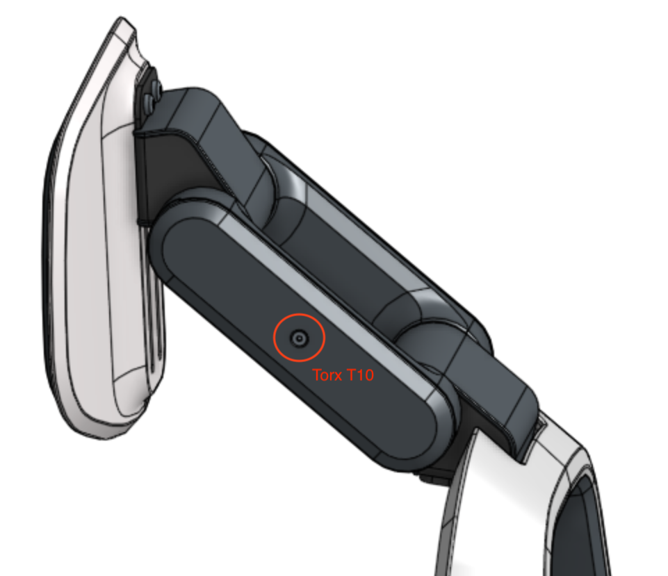 (a) Remove covering | 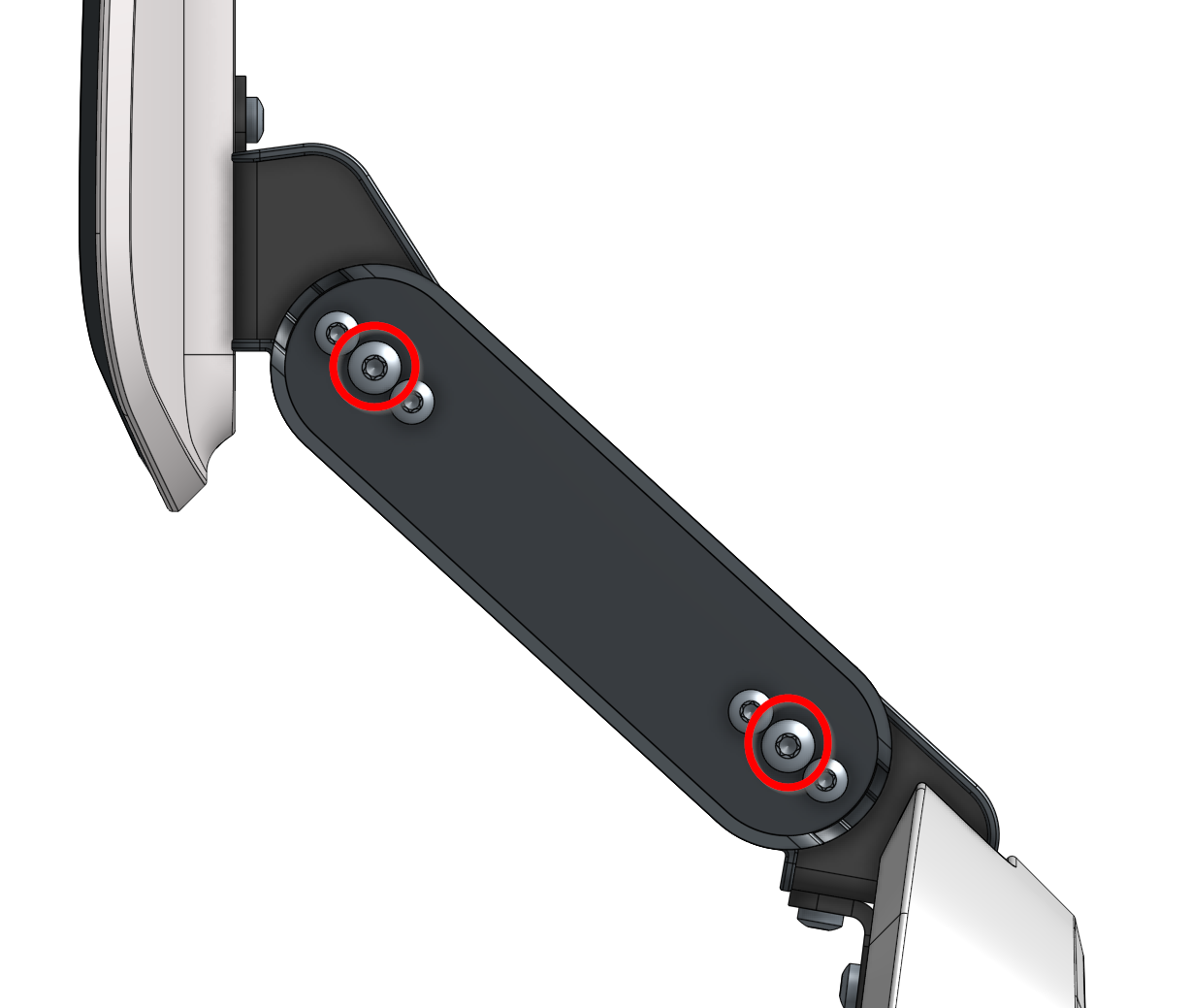 (b) Adjust the angle | 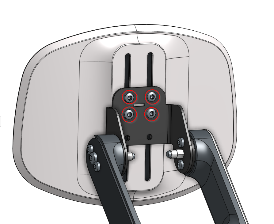 (c) Adjust the height |